
Advanced Guide#
This area contains detailed technical discussion related to kdFlex architecture and design.
Multibody root frames#
The frames layer (Frames Layer section) forms a foundational
layer for the kdFlex software that the multibody model definition
builds upon. The instance provides a root frame that serves as the unique anchor for the rest of the frames in the system.
As described in {ref}{multibodytop_sec section), the multibody model
consists of a collection of physical body connected by is a virtual root body that is automatically created by the
instance. This section focuses on intermediate frames between the
root frame and the virtual root body including:
Newtoninan frame: The Newtonian frame is the frame that is used as the inertial frame when carrying out dynamics computations. For this purpose, the Newtonian frame is regarded as a non-accelerating and a non-rotating frame. kdFlex allows any frame upstream of the virtual root body be designated as a Newtonian frame, with the understanding that all rotational velocities and linear accelerations upstream of this frame will not be factored into the dynamics computations.Multibody root frame: The multibody frame is downstream of theNewtonianframe and is typically the parent of the virtual root body. It’s typical use is to serve as a local frame that allows for the use of reasonable values for the generalized coordinates for the multibody system.
When the frames are distinct, the frame container root frame is upstream of the Newtonian frame, which is upstream of the multibody root frame, which upstream of the virtual root body, which in turn is upstream of all the body and nodes defined in the multibody system.
We now present some illustrative examples to illustrate the choice of these frames when creating the multibody model.
Root frame = Newtonian frame = Multibody root frame#
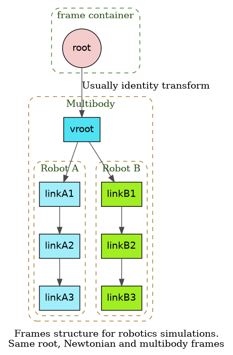
This is the simplest scenario where the virtual root body is directly connected to the root frame, which also serves as the Newtonian and the multibody root frame. A good use case for this are unit tests for multibody systems as well as for robotics types scenarios. The following illustrates an example of the frame hierarchy for a robotics simulation.
![digraph multi_node_cutjoint {
// Enable ranking across cluster boundaries
newrank=true;
// Draw the original parent-to-child direction from top to bottom.
title="AAAA";
graph [bgcolor="transparent", rankdir=TB, nodesep=0.45, ranksep=0.55,
label="Frames structure for robotics simulations.\nSame root, Newtonian and multibody frames"];
node [shape=circle, style=filled, fontname="Helvetica"];
edge [color="#4a4a4a"];
// frame container root
subgraph cluster_fc {
label="frame container";
color="#38761d";
fontcolor="#274e13";
style="dashed,rounded";
root [label="root", fillcolor="#f4cccc"];
}
subgraph cluster_mb {
label="Multibody";
color="#98761d";
fontcolor="#274e13";
style="dashed,rounded";
vroot [fillcolor="#4fe2f3", shape="box"];
// vehicle frames
subgraph cluster_vehicle1 {
label="Robot A";
color="#98761d";
fontcolor="#274e13";
style="dashed,rounded";
link1 [label="linkA1", fillcolor="#a1eefa", shape="box"];
link2 [label="linkA2", fillcolor="#a1eefa", shape="box"];
link3 [label="linkA3", fillcolor="#a1eefa", shape="box"];
}
subgraph cluster_vehicle2 {
label="Robot B";
color="#98761d";
fontcolor="#274e13";
style="dashed,rounded";
linkB1 [label="linkB1", fillcolor="#a1ee22", shape="box"];
linkB2 [label="linkB2", fillcolor="#a1ee22", shape="box"];
linkB3 [label="linkB3", fillcolor="#a1ee22", shape="box"];
}
}
root -> vroot [label="Usually identity transform"];
vroot -> link1;
link1 -> link2;
link2 -> link3;
vroot -> linkB1;
linkB1 -> linkB2;
linkB2 -> linkB3;
}](_images/graphviz-b4214803d451ff49d0144454d5c1d9aaf90cb6ca.png)
Root frame != Newtonian frame = Multibody root frame (non-rotating)#
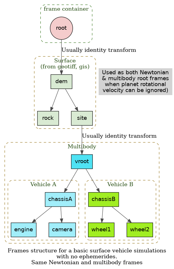
In this scenario, while the Newtonian frame and multibody frames are the same, they are distinct from the root frame. The basic ground vehicle simulation scenario described below illustrates this situation. The simulation involves simulating the dynamics of a ground vehicle at a specific site. The terrain surface DEM has a local frame, which is attached to the root frame, and serves as the Newtonian and multibody frames for the simulation. As defined, the multibody frame does not move.
![digraph multi_node_cutjoint {
// Enable ranking across cluster boundaries
newrank=true;
// Draw the original parent-to-child direction from top to bottom.
title="AAAA";
graph [bgcolor="transparent", rankdir=TB, nodesep=0.45, ranksep=0.55,
label="Frames structure for a basic surface vehicle simulations\nwith no ephemerides.\nSame Newtonian and multibody frames"];
node [shape=circle, style=filled, fontname="Helvetica"];
edge [color="#4a4a4a"];
// frame container root
subgraph cluster_fc {
label="frame container";
color="#38761d";
fontcolor="#274e13";
style="dashed,rounded";
root [label="root", fillcolor="#f4cccc"];
}
// surface frames
subgraph cluster_surface {
label="Surface\n(from geotiff, gis)";
color="#98761d";
fontcolor="#274e13";
style="dashed,rounded";
dem [fillcolor="#d9ead3", shape="box"];
rock [fillcolor="#d9ead3", shape="box"];
site [fillcolor="#d9ead3", shape="box"];
}
surface_text [label="Used as both Newtonian\n& multibody root frames\nwhen planet rotational\nvelocity can be ignored)", shape=plaintext];
// Force them on the same rank
{ rank=same; dem; surface_text; }
subgraph cluster_mb {
label="Multibody";
color="#98761d";
fontcolor="#274e13";
style="dashed,rounded";
vroot [fillcolor="#4fe2f3", shape="box"];
// vehicle frames
subgraph cluster_vehicle1 {
label="Vehicle A";
color="#98761d";
fontcolor="#274e13";
style="dashed,rounded";
chassisA [fillcolor="#a1eefa", shape="box"];
engine [fillcolor="#a1eefa", shape="box"];
camera [fillcolor="#a1eefa", shape="box"];
}
subgraph cluster_vehicle2 {
label="Vehicle B";
color="#98761d";
fontcolor="#274e13";
style="dashed,rounded";
chassisB [fillcolor="#a1ee22", shape="box"];
wheel1 [fillcolor="#a1ee22", shape="box"];
wheel2 [fillcolor="#a1ee22", shape="box"];
}
}
root -> dem [label="Usually identity transform"];
dem -> rock;
dem -> site;
site -> vroot [label="Usually identity transform"];
vroot -> chassisA;
chassisA -> engine;
chassisA -> camera;
vroot -> chassisB;
chassisB -> wheel1;
chassisB -> wheel2;
}](_images/graphviz-eebcf8a7074c8c87d7784405969693dfc16a6642.png)
Root frame != Newtonian frame = Multibody root frame (rotating)#
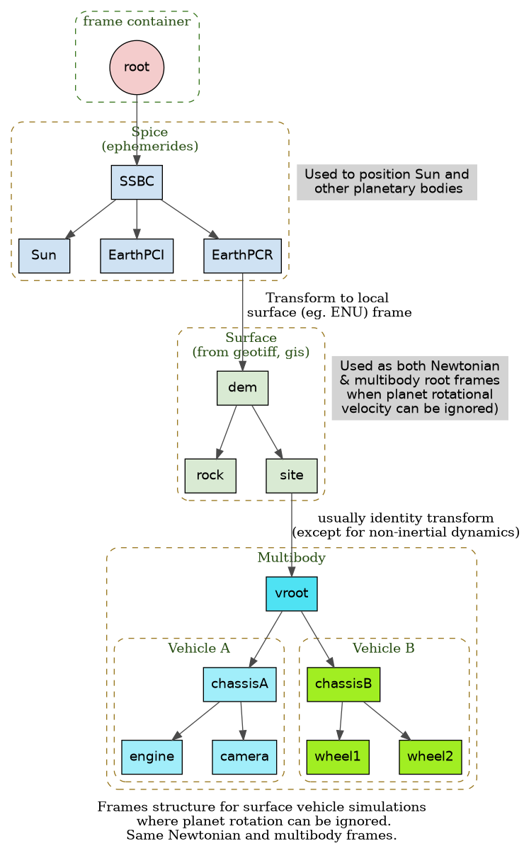
This scenario is a variant of the ground vehicle simulation described
above, but where the sun direction and its motion with time is included
in the simulation since it changes the lighting and shadows. To meet
this need, the simulation includes ephemerides for planetary bodies via
the Spice toolkit. The terrain surface DEM (possibly obtained from a
geotiff file) is attached to the surface of a planetary body such as
the rotating Earth. The planet center attached rotating frame is
referred to as the planet centered rotating (PCR) frame. Since the PCR
frame is a rotating frame - it is not strictly speaking an inertial
frame. As a consequence, the surface terrain frame is not an inertial
frame either. However, the non-inertial contributions from the PCR
rotation are small, and can times be neglected. Continuing to choose the
surface terrain frame as the Newtonian and multibody root frames omits
these non-inertial contributions to the system dynamics. The
ephemerides is only used to update the locations of the celestial bodies
as needed by the lighting models. Note that the PCR frame could also
have been used for the Newtonian and multibody root frames without
changing the dynamics, but with the downside that the coordinates needed
to define the location of the ground vehicle would be inconveniently
large to include the distance from the center of the planetary body.
The frame hierarchy for this is shown below.
![digraph multi_node_cutjoint {
// Enable ranking across cluster boundaries
newrank=true;
// Draw the original parent-to-child direction from top to bottom.
title="AAAA";
graph [bgcolor="transparent", rankdir=TB, nodesep=0.45, ranksep=0.55,
label="Frames structure for surface vehicle simulations\n where planet rotation can be ignored.\nSame Newtonian and multibody frames."];
node [shape=circle, style=filled, fontname="Helvetica"];
edge [color="#4a4a4a"];
// frame container root
subgraph cluster_fc {
label="frame container";
color="#38761d";
fontcolor="#274e13";
style="dashed,rounded";
root [label="root", fillcolor="#f4cccc"];
}
// spice frames
subgraph cluster_spice {
label="Spice\n(ephemerides)";
color="#98761d";
fontcolor="#274e13";
style="dashed,rounded";
SSBC [fillcolor="#cfe2f3", shape="box"];
Sun [fillcolor="#cfe2f3", shape="box"];
EarthPCI [fillcolor="#cfe2f3", shape="box"];
EarthPCR [fillcolor="#cfe2f3", shape="box"];
}
spice_text [label="Used to position Sun and\n other planetary bodies", shape=plaintext];
// Force them on the same rank
{ rank=same; SSBC; spice_text; }
// surface frames
subgraph cluster_surface {
label="Surface\n(from geotiff, gis)";
color="#98761d";
fontcolor="#274e13";
style="dashed,rounded";
dem [fillcolor="#d9ead3", shape="box"];
rock [fillcolor="#d9ead3", shape="box"];
site [fillcolor="#d9ead3", shape="box"];
}
surface_text [label="Used as both Newtonian\n& multibody root frames\nwhen planet rotational\nvelocity can be ignored)", shape=plaintext];
// Force them on the same rank
{ rank=same; dem; surface_text; }
subgraph cluster_mb {
label="Multibody";
color="#98761d";
fontcolor="#274e13";
style="dashed,rounded";
vroot [fillcolor="#4fe2f3", shape="box"];
// vehicle frames
subgraph cluster_vehicle1 {
label="Vehicle A";
color="#98761d";
fontcolor="#274e13";
style="dashed,rounded";
chassisA [fillcolor="#a1eefa", shape="box"];
engine [fillcolor="#a1eefa", shape="box"];
camera [fillcolor="#a1eefa", shape="box"];
}
subgraph cluster_vehicle2 {
label="Vehicle B";
color="#98761d";
fontcolor="#274e13";
style="dashed,rounded";
chassisB [fillcolor="#a1ee22", shape="box"];
wheel1 [fillcolor="#a1ee22", shape="box"];
wheel2 [fillcolor="#a1ee22", shape="box"];
}
}
root -> SSBC;
SSBC -> Sun;
SSBC -> EarthPCI;
SSBC -> EarthPCR;
EarthPCR -> dem [label="Transform to local\n surface (eg. ENU) frame"];
dem -> rock;
dem -> site;
site -> vroot [label="usually identity transform\n(except for non-inertial dynamics)"];
vroot -> chassisA;
chassisA -> engine;
chassisA -> camera;
vroot -> chassisB;
chassisB -> wheel1;
chassisB -> wheel2;
}](_images/graphviz-1f465b34a069c2b0cb66df896741a2068ef83dcf.png)
Root frame != Newtonian frame != Multibody root frame#
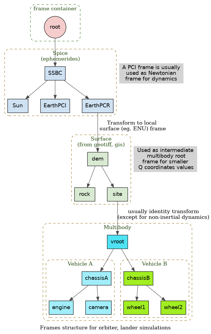
There are times where the inertial effects cannot be ignored. This would
be case if the previous scenario involved an orbiter or lander vehicle.
To obtain a suitable frame to use as inertial frame for dynamics
computation, the normal practice is to define a planet centered inertial (PCI) frame that is a non-rotating frame co-located with the
PCR frame. In this scenario, the PCI frame is used as the the Newtonian
frame, and the surface terrain frame as the multibody frame. This is the most general case and illustrated in the figure below.
![digraph multi_node_cutjoint {
// Enable ranking across cluster boundaries
newrank=true;
// Draw the original parent-to-child direction from top to bottom.
title="AAAA";
graph [bgcolor="transparent", rankdir=TB, nodesep=0.45, ranksep=0.55, label="Frames structure for orbiter, lander simulations"];
node [shape=circle, style=filled, fontname="Helvetica"];
edge [color="#4a4a4a"];
// frame container root
subgraph cluster_fc {
label="frame container";
color="#38761d";
fontcolor="#274e13";
style="dashed,rounded";
root [label="root", fillcolor="#f4cccc"];
}
// spice frames
subgraph cluster_spice {
label="Spice\n(ephemerides)";
color="#98761d";
fontcolor="#274e13";
style="dashed,rounded";
SSBC [fillcolor="#cfe2f3", shape="box"];
Sun [fillcolor="#cfe2f3", shape="box"];
EarthPCI [fillcolor="#cfe2f3", shape="box"];
EarthPCR [fillcolor="#cfe2f3", shape="box"];
}
spice_text [label="A PCI frame is usually\nused as Newtonian\nframe for dynamics", shape=plaintext];
// Force them on the same rank
{ rank=same; SSBC; spice_text; }
// surface frames
subgraph cluster_surface {
label="Surface\n(from geotiff, gis)";
color="#98761d";
fontcolor="#274e13";
style="dashed,rounded";
dem [fillcolor="#d9ead3", shape="box"];
rock [fillcolor="#d9ead3", shape="box"];
site [fillcolor="#d9ead3", shape="box"];
}
surface_text [label="Used as intermediate\n multibody root\nframe for smaller\n Q coordinates values", shape=plaintext];
// Force them on the same rank
{ rank=same; dem; surface_text; }
subgraph cluster_mb {
label="Multibody";
color="#98761d";
fontcolor="#274e13";
style="dashed,rounded";
vroot [fillcolor="#4fe2f3", shape="box"];
// vehicle frames
subgraph cluster_vehicle1 {
label="Vehicle A";
color="#98761d";
fontcolor="#274e13";
style="dashed,rounded";
chassisA [fillcolor="#a1eefa", shape="box"];
engine [fillcolor="#a1eefa", shape="box"];
camera [fillcolor="#a1eefa", shape="box"];
}
subgraph cluster_vehicle2 {
label="Vehicle B";
color="#98761d";
fontcolor="#274e13";
style="dashed,rounded";
chassisB [fillcolor="#a1ee22", shape="box"];
wheel1 [fillcolor="#a1ee22", shape="box"];
wheel2 [fillcolor="#a1ee22", shape="box"];
}
}
root -> SSBC;
SSBC -> Sun;
SSBC -> EarthPCI;
SSBC -> EarthPCR;
EarthPCR -> dem [label="Transform to local\n surface (eg. ENU) frame"];
dem -> rock;
dem -> site;
site -> vroot [label="usually identity transform\n(except for non-inertial dynamics)"];
vroot -> chassisA;
chassisA -> engine;
chassisA -> camera;
vroot -> chassisB;
chassisB -> wheel1;
chassisB -> wheel2;
}](_images/graphviz-21f4da13ab495cea362f898d51351f78d6ef7b11.png)
Partitioned integrators#
Karana.Integrators.createIntegrator() takes num_q_states immediately
after num_states. The state layout is [Q, U]: the first num_q_states entries
are Q and the remaining entries are U. Ordinary integrators store this count
but do not use the partition; pass zero when it is unspecified. Every integrator
requires num_q_states <= num_states. The
Karana.Integrators.Integrator.nQ() getter returns the
stored count. Karana.Integrators.Integrator.hardReset()
takes both dimensions, while a soft reset preserves them.
Karana.Integrators.PartitionedIntegrator is abstract and requires
nonempty Q and U blocks for a nonempty system. An empty system uses both counts
set to zero and advances time without evaluating derivatives.
Karana.Integrators.ExplicitVerletIntegrator uses explicit
kick–drift–kick steps. Each advanceTo call takes one step over the requested
interval. Second-order accuracy requires separable equations Qdot = f(U) and
Udot = g(t, Q). Q and U may have different sizes. Coordinate-dependent Q rates
and velocity-dependent forces fall outside this contract; the integrator cannot
check those dependencies from the callback.
For a unit harmonic oscillator:
import Karana.Core as kc
import Karana.Integrators as ki
import numpy as np
def oscillator(time: object, state: np.ndarray, derivative: np.ndarray) -> bool:
"""Write [U, -Q] into derivative for state=[Q, U]; time is unused; return True."""
derivative[0] = state[1]
derivative[1] = -state[0]
return True
integrator = ki.createIntegrator(ki.IntegratorType.EXPLICIT_VERLET, 2, 1, oscillator)
try:
integrator.softReset(0.0, np.array([1.0, 0.0]))
for step in range(1, 101):
integrator.advanceTo(step / 100)
print(integrator.getX())
finally:
kc.discard(integrator)
Manual construction calls must supply the new argument, and dependent C++ libraries must be rebuilt. StatePropagator integration also requires its factory and hard-reset calls to supply the Q count of the actual packed layout.